Support
If you have any questions or comments, please contact our support technicians.
| Hours: | Monday - Friday |
| 8:00am - 5:00pm (Central Time) | |
| Email: | pulsesupport@genesisworld.com |
| Phone: | 903-787-7400 |
| Web: | genesisworld.com/support |
If you have any questions or comments, please contact our support technicians.
| Hours: | Monday - Friday |
| 8:00am - 5:00pm (Central Time) | |
| Email: | pulsesupport@genesisworld.com |
| Phone: | 903-787-7400 |
| Web: | genesisworld.com/support |
Genesis PULSE® revolves around the Tracking page and its ability to provide real-time resource tracking and analysis.
The Tracking Page provides users with real-time Unit and Incident location data, as well as, widgets that provide valuable insights into the data being shown.
The major components that make up the Tracking Page are as follows:
- Google Map Controls - These are controls provided by Google
- Icon Glossary - Defines all icons that will be visible on the Tracking Page.
- Location Data
- Assets - Assets, such as radios, are displayed using their real-time location.
- Units - Units are displayed using their real-time location.
- Incidents - Incidents will be shown as they occur.
- Post Locations - PULSE Live will pull post plans from the configured CAD and display them.
- Map Pages - Map Pages are used to show a general area of an Incident when there is no available address.
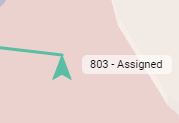
- Mission Lines - Mission lines link the Units to their destination.
- Stop Points - Stop Points show the actual location a unit needs to go to for a previously visited location.
- Closest Units - Shows the three closest Units (by Type) to a specific incident or to a specific unit’s current location.
- Widget Bar - Menu bar providing access to the map widgets
- Widgets
- Active Responses - Shows data for all active responses
- Active Units - Shows data for all active units
- Asset Layer - Toggles Assets on/off
- Unit Recommendations - Shows the closest available units for in-queue incidents
- Custom Layers - Toggle Custom Layers on/off
- Last updated - Shows last time data was received from the CAD
- Map Pages - Shows all map pages as a layer with configurable opacity and color.
- Optional Statuses - Toggle Units on/off based on their status
- Post Geofencing - Shows Post Geofencing violations
- Radio Assets - Shows all assets that are eligible to show on the map based on Pulse admin asset timeout setting.
- RapidSOS Activity - Shows RapidSOS activity related to incidents, including RapidSOS Location information and MedicAlert information.
- Saved Views - Allows specific position and zoom level on the map to be saved
- Scheduled Calls in Queue - Shows upcoming scheduled calls for the current day and the next
- Waze Traffic Collisions - Shows traffic collisions reported via the Waze integration
- Weather Layer - Shows weather information provided via the Aeris integration
- Zone Layers - Toggle Zone Layers on/off
The Google Map Controls are controls that are provided by Google to aid in navigating the map.
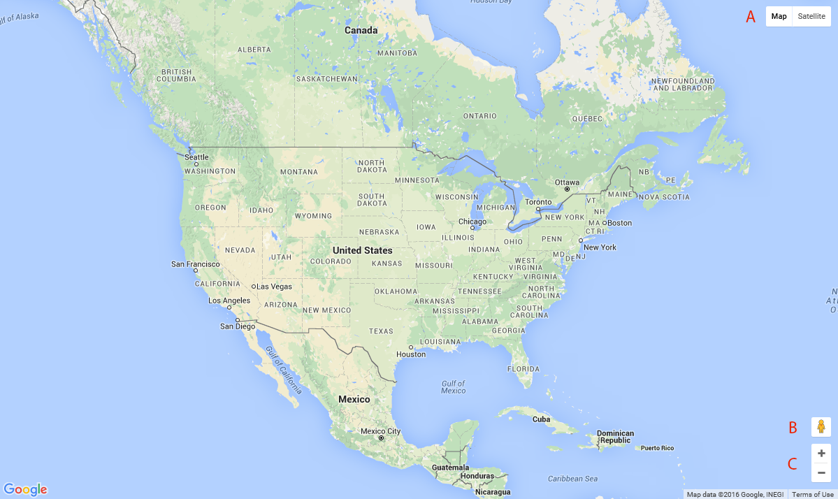
Google provides 2 map layers each with their own variations.
The variation on this layer that the control allows you to toggle is to enable terrain (topology).
The control allows you to toggle between the default satellite imagery with layers and without layers.
By dragging and dropping the Street View icon onto the map you will enter Street View mode which allows you to see photos taken at ground level.
The zoom control allows the map's altitude to be changed. The same functionality is available by using the scroll wheel on a mouse or by pinching on touch devices.
PULSE Live uses a set of easily identifiable icons across the site. Below is a glossary of these icons detailing what should be expected when they are seen.
The vehicle icon shows where a unit is currently located and what direction it is headed. The tip of the icon points to the exact location of the unit, and the icon will rotate around that point to show the appropriate compass direction.
The color of the icon is based on the unit's status unless the unit is responding to an incident. If the unit is responding to an incident then the color is based on the priority of the response. The colors can be configured on the Unit Statuses and Priority management pages.
The asset icon shows where an asset is currently located.
The asset emergency icon shows where an asset in the emergency state is currently located.
The Late call Indicator is used to show a unit with contractual obligations was late responding to an incident. The icon will appear once any unit responding to the call checks on scene and is considered late. At this time all units assigned to the call and obligated to respond within a certain period will receive the icon. The color of the square will match the vehicle icon.
The Violation Icon appears in the Label and Information Window of units that are in violation of a contractual obligation.

The Layer Delay Icon appears in the ETE column of the Unit Recommendations widget when the unit being recommend is inside of a Custom Layer which has been configured with a delay.

The Stale GPS Icon appears in the Label and Information Window of units whose last GPS update is older than the GPS threshold. By default this is two hours. The setting is configurable on the Unit Statuses page.

The Invalid GPS Icon appears in the Label and Information Window of units whose last GPS update was invalid. GPS updates with a latitude of 0 and a longitude of 0 are considered invalid.
The In-Queue Incident icon appears when a new Incident occurs. The icon will be colored based on the Incident's priority, which can be configured on the Priority management page.
The Scene Location / Destination icon indicates a unit's destination when the unit is responding to an incident. It will replace the In-Queue icon of the incident once a unit is assigned to it, and then appear at the unit's transport destination after the unit begins transporting.
The color of the icon is based on the Priority of the response and can be configured on the Priority management page.
The Post/Station icon represents the posts currently in the active Posting Plan. The color of the Post/Station icon can be configured in the Post management page.
A stop point icon indicates the actual location to which a unit should navigate to when responding to a call. These should be used when the given coordinates of a location does not correspond to the actual entrance or pickup location (e.g., coordinates represent center of a facility instead of its entrance).
Mission lines link Units to their destination. The color and width of the Mission Lines is dependent on the Unit's status if it is not currently in a response, otherwise it is based on the Priority of the response.
The color and weight can be configured on the Unit Statuses and Priority management pages.
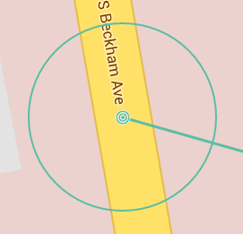
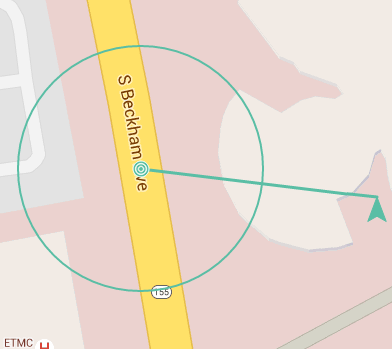
The VRC icon is a constricting circle that will appear when an incident occurs that matches the requirements of a configured standard on a contract. The circle will constrict around the incident as the amount of remaining time is reduced. The area within the circle indicates the approximate distance from the incident a unit can be and still make it within the remaining time.
The distance is based on the fastest Travel Mode of the incident's assigned units. An average speed is used to calculate the distance and is defined by the Travel Mode Speed on the incident's layer.
The Driving Travel Mode is used by default.
The color matches the Priority of the incident, which can be configured on the Priority management page.
Map Pages are another means for showing incidents on the map. The color is based on the incident's priority.
See the Map Pages section for details.
Labels appear next to most icons to aid in identifying resources. For detailed information explaining what will be visible for a given resource navigate to the respective resource within the Tracking chapter.
Information Windows are similar to the Labels, but they provide more detailed information about the state of a given resource. To view information windows simply click on the desired resource.
Please note that not all resources have information windows. To see if a resource has an information window and details about what they will display see the respective section for the resource under the Location Data section.
Also, PULSE Live can only display data that the CAD has available, thus sometimes all of the data that the Information Window is capable of displaying is not present. If the data was not received for a specific field that may usually be displayed in the information window, PULSE Live will not display said field.
The location data that is displayed by PULSE Live can represent assets, points of interest, events, or visual indicators.
PULSE is capable of managing and tracking assets that originate from a source that provides asset and location information.
Sources compatible with PULSE include:
Assets are visible at set zoom levels. A global zoom level (per dispatch center) controls the minimum zoom level at which assets become visible on the map. The local PULSE Administrator can contact PULSE Support for adjusting the global zoom levels.
Asset type zoom level controls the level at which assets with that specific type become visible. This level is considered only when it is greater than the global zoom. Asset type zoom level can be set from the Asset Types page. For more information on viewing assets see the Assets section under Widgets.
If an asset has not issued a location update within the timeout period, the asset will be excluded from tracking. The timeout period is specific to your dispatch center. The local PULSE Administrator can contact PULSE Support for adjusting the asset location update timeout period.
Assets use labels and information windows to show information about their current state.
Label - The asset label provides a snapshot of the asset's current state and displays the asset's alias if it is available, else it shows the asset's display name. If the asset is in the emergency state, the label will include an emergency icon and the text "(emergency)"
Information Window - The information window provides a more comprehensive view of the asset's state and is broken up into a few different sections:
Units shown on the Tracking page use real-time coordinates from the connected CAD system for active units.
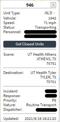
The units use Labels and Information Windows to show information about the unit's current state.
Label - The label provides a snapshot of the Unit's current state, and displays the following information:
When the remaining EOS time runs out the label will be modified to use white text on a black background to indicate that the unit is at the end of their shift.
Information Window - The information window provides a more comprehensive view of the unit's state and is broken up into a few different sections.
Tracking [Edit Unit Type] permission will be able to
modify the unit type here. Additionally, the unit type can be
configured on the Unit
management page.
Incidents on the Tracking page use real-time data pulled from the connected CAD system.
The incidents use Labels and Information Windows to show information about the incident's current state.
Label - the label simply displays the incident's Job Number that identifies it until a Run Number is assigned at which point the Run Number is displayed. These values are pulled directly from the CAD.
Information Window - the information window provides detailed information about the incident and is broken into several section, including:
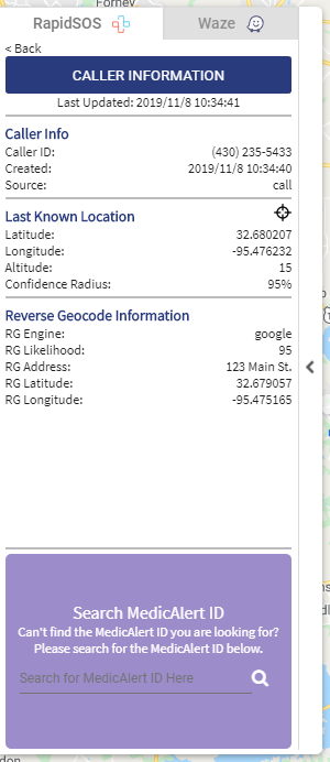
Precise Location - This icon ![]() displays precise location and meta data from the caller's device.
This information is provided by RapidSOS.
displays precise location and meta data from the caller's device.
This information is provided by RapidSOS.
Posts on the Tracking page reflect the current posting plan on the CAD.
The Post icons use labels to aid in identification. The label will have the post's name or alias if it exists. The alias can be configured on the Post management page.
Please note that posts do not make use of information windows.
Map Pages are used to show a general area for an incident if the incident doesn't have a geocoded address.
The map pages do make use of labels and information windows.
Labels - the labels simply display the Job/Run number of the incident that the map page represents.
Information Window - the information window also shows the Job/Run Number of the incident as well as the priority of the incident. The Priority field will display the name of the priority or the alias if it exists. The alias can be configured on the Priority management page.
Please note that map pages are only available for CADs that have the ability to configure and use map pages.
Mission lines are visual indicators that aid in quickly identifying where a unit is heading by providing a line-of-sight connecting line between a unit and its destination.
By default, the mission line will be colored based on the unit's status, which can be configured on the Unit Statuses management page. If the unit status is configured for it, the mission line will instead use the priority color when the unit is responding to an incident.
Stop points allow a user (with proper access) to add a marker to the map indicating where a specific driveway or entrance is to a particular address. The next time a unit is dispatched to this same address, PULSE will display a mission line to the geocoded location provided by CAD and will also display a dashed mission line indicating the location of the previously set stop point.
To add a stop point, a unit must have an 'At Scene' status. Clicking on the unit will display the Vehicle Info Window. Clicking on the ‘Set Stop Point’ button will cause a new stop point to be created. The map will be updated to show the new stop point.
When the desired unit enters an 'At Scene' status, click the unit to open the Info Window. Then, click the ‘Move Stop Point’ button. The user will be asked to verify the removal of the current stop point and the creation of a new one based on the unit's current location.
To delete a stop point, click on the active stop point and then click the ‘Delete Stop Point’ button. A verification message will confirm you want to remove the current stop point. Click yes, if so, and the stop point will be removed.
To add or move the stop point the unit must be in an 'At Scene' status, and it cannot be at the exact location of the incident. If either of these is not true then the `Add/Move Stop Point` buttons will not be available.
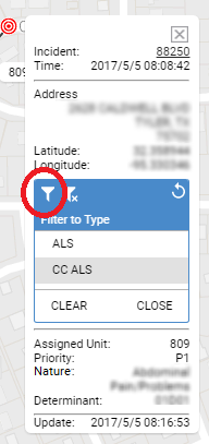
To see the closest units, go to an incident/unit Info Window and click on the Get Closest Units button.
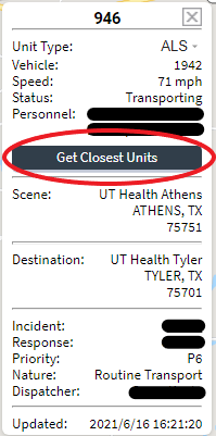
Closest Units allows the dispatcher to see the closest three available units to any incident or unit based on actual travel mode time, including real-time traffic patterns where appropriate, from the unit's current position to the unit or incident selected.
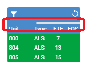
The columns in the window are color coded to provide a visual representation of available units.
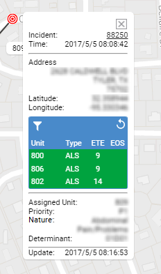
The ETE column indicates the Estimated Time Enroute, in
minutes, for each unit. This is based on the travel mode of the unit.
In rare cases, actual drive time may not be available, in which
case the ETE is calculated using an 'as-the-crow-flies' distance between
the current positions of the incident and unit with an average speed of
25 mph. Any such 'Line of Sight' ETEs will be marked with an asterisk and
hovering over the ETE will show a tooltip stating the ETE is calculated
based on line of sight.
Line of Sight (Air) has a default average speed of 115 mph
Line of Sight (Ground) has a default average speed of 45 mph
The EOS column indicates the amount of time, in minutes,
before a unit/personnel is expected to complete their assigned shift. This
information is based on the end-of-shift information available/entered
into the connected CAD system, and the threshold settings set by the
PULSE Administrator in the EOS information window in the Configuration page.
Filter Button: By default the closest 3 units overall will be shown. The filter button is used to
filter the list down to the top 3 units of the selected type.
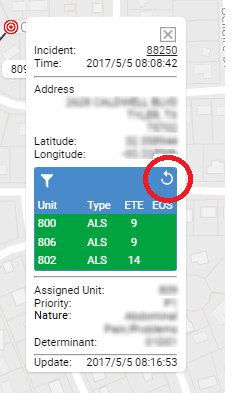
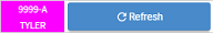
Once closest units have been loaded, they will be displayed until they are no longer valid. A timer will be shown to indicate when the data will be cleared. If you click on the refresh button, the timer will reset and start again once the list has been updated.
The Widget Panel manages all widgets used on the Tracking page. The panel allows the user to enable the desired widgets. Most widgets will be displayed within the panel on the right side of the page.
The Widget Bar is made up of several components: the trigger icon, the panel that contains the widgets, and the menu bar.

By default, the Widget Bar is hidden off to the right of the page. By clicking on the trigger icon, the widget bar expands for use.
Note that the trigger icon collapses when the Widget Bar is visible.
The widget panel provides a place for the widgets to be displayed when they are docked. There are two types of widgets: docked and independent.
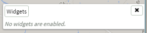
You'll find the Widgets and X buttons on the
menu bar.
Widgets
X
Widgets on the Tracking page provide varying functionality based on the live data being displayed on the map.
All map widget settings are user based.
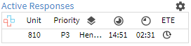
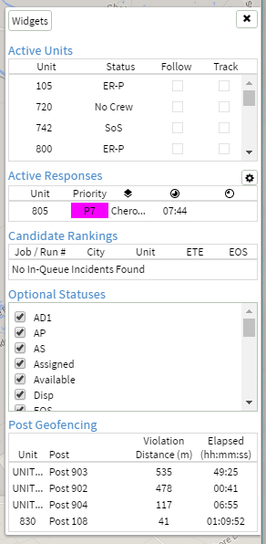
Each row in the widget represents a response. An icon appears if the call has supplemental data from RapidSOS. Each response also includes the unit name, current response priority, map layer/zone where incident was geocoded in CAD, amount of time unit has been in current status (Elapsed), and amount of time remaining before call/incident is considered late by the standards set in the Contracts management page. You can choose to track the estimated time enroute (ETE) by clicking on the clock image in the ETE column. If you choose to show the ETE by clicking on the clock icon, the ETE for this unit will show for a period of time just under three minutes. Clicking on a unit will center the map on that unit and animate the unit's icon for two seconds.
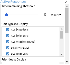
Remaining time column is equal to or less than
this set value. See unit 831 in the
Active Responses Widget image above.
It is important to note that these filters only filter the response from the widget, not the map.
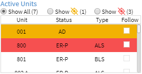
Displays all active units along with their types in alphabetical order and gives their current status.
The colors of the rows on the Active Units widget provide information related to unit's GPS status:
The Active Units widget provides the following important functions for interacting with units:
Go To functionality
with the added benefit of actively following the unit as it updates by
keeping the map centered on the unit.
This feature can only be enabled for one unit at a time.
Assets provides location information for assets tracked by PULSE.
To use this feature, go to the Layer Bar and click on “Assets”.
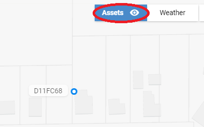
NOTE: The Assets layer bar option is only available if Asset information is stored for your dispatch center within PULSE.
Assets are shown on the PULSE tracking map only if:
When the Assets layer bar option is enabled, the Assets button is blue. When the option is disabled, the Asset button is white.
The eye icon in the Asset layer bar option indicates if you are at an appropriate zoom level to see assets. If you are not zoomed in close enough, the eye is gray. If you are zoomed in close enough, the eye is white. The local PULSE Administrator can contact PULSE Support for adjusting the zoom level.
This widget is not enabled by default. To enable it, go to the Configuration management page and check the option to enable it.
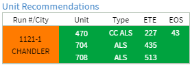
Unit Recommendations allow the dispatcher to quickly see the closest available units to any in-queue incident based on actual travel mode time, including real-time traffic patterns , from the unit's current position to the geocoded scene location.
Unit Recommendations can also be filtered automatically based on the call type to unit type configurations, see the Call Types Tab section for more information. These configurations can be overriden by selecting/deselecting the unit type filters.
The columns in the widget are color coded to provide a visual representation of the severity of the incidents and the status of the available units.
The Run #/City column is color coded using the priority of the incident so
that the dispatcher can see quickly if a high priority incident still
needs to be dispatched. The colors can be configured on the
Priority management page.
The Unit, Type, ETE, and EOS columns are color
coded using each unit's color. The unit's color may be based on its
priority or its status. The unit status colors can be set on the
Unit Statuses management page.
The ETE column indicates the Estimated Time Enroute, in
minutes, for each unit. This is based on the travel mode of the unit.
In rare cases, actual drive time may not be available, in which
case the ETE is calculated using an 'as-the-crow-flies' distance between
the current positions of the incident and unit with an average speed of
25 mph. Any such 'Line of Sight' ETEs will be marked with an asterisk and
hovering over the ETE will show a tooltip stating the ETE is calculated
based on line of sight.
Driving mode includes real-time traffic patterns
Line of Sight (Air) has a default average speed of 115 mph
Line of Sight (Ground) has a default average speed of 45 mph
The ETE column may also have an icon indicating one of the following:
The EOS column indicates the amount of time, in minutes,
before a unit/personnel is expected to complete their assigned shift. This
information is based on the end-of-shift information available/entered
into the connected CAD system, and the threshold settings set by the
PULSE Administrator in the EOS information window in the
Configuration page.
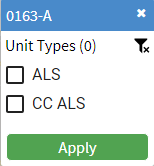
 , select the desired type(s) within the Filter Menu, then click the 'Apply' button.
Upon clicking 'Apply', you may see the Unit Recommendation enter a "refreshing" state
as PULSE recalculates recommendations. To clear a Unit Recommendation's Unit Type Filter,
click the clear filter(s) button
, select the desired type(s) within the Filter Menu, then click the 'Apply' button.
Upon clicking 'Apply', you may see the Unit Recommendation enter a "refreshing" state
as PULSE recalculates recommendations. To clear a Unit Recommendation's Unit Type Filter,
click the clear filter(s) button
 then click the 'Apply' button. Applying a filter to an expired Unit Recommendations will refresh
Unit Recommendations and reflect the selected filters.
The number "(0)" by the "Unit Types" header represents the number of Unit Types selected.
then click the 'Apply' button. Applying a filter to an expired Unit Recommendations will refresh
Unit Recommendations and reflect the selected filters.
The number "(0)" by the "Unit Types" header represents the number of Unit Types selected.
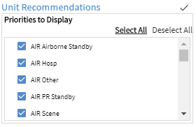
It is important to note that these filters filter the incidents from the widget and the map.
These settings are not saved when the tracking page is closed.

Places a date/timestamp widget in the bottom left corner of the PULSE Live window allowing PULSE users to confirm data is actively being passed from the CAD server to the PULSE server.
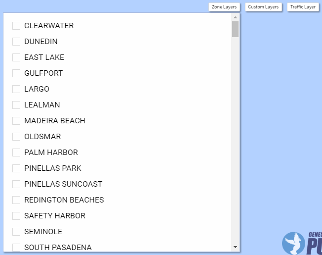
There are 3 layer controls to be aware of: Zone, Custom, and Traffic.
The Zone and Custom Layers controls operate the same way. Click on one, and you will see a list expand below the control with all available Zone and Custom layers respectively.
With the list expanded, desired layers can be added or removed from the map as necessary.
To close the list, click the Zone or Custom Layer control again.
The Traffic Layer control is a bit different in that it is a simple toggle switch. Click it and Google's traffic layer will be enabled.

The Map Page widget provides a way to show or hide all possible map pages as a single layer on the map.
The widget has several options for manipulating the Map Page layer.
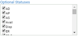
Show units / incidents on the PULSE Live map based on a units' assigned status. In order for a status to populate in this widget, the PULSE Administrator must enable each status within the Unit Statuses management page.
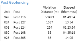
Geofencing defines a radius around a post to quickly see when a vehicle or asset is in violation of an established geofence. Violation distance is in meters and is measured from the outer ring of the geofence boundary to the position of the vehicle/asset. The Elapsed column indicates the amount of time that the unit has spent outside of its post location. (For details on establishing geofences, see the Post management page.)
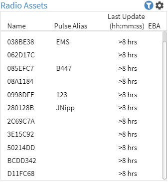
Displays basic information about assets such as their name, type, last update and EBA (Emergency Button Activation). The EBA button is shown if an asset is currently in the emergency state, or will show the greyed out icon if the asset was in the emergency state within the previous 30 minutes.
This widget provides the ability for interacting with assets.
(For details about Assets, see the Assets management page.)
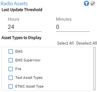
When the list is filtered, the blue filtering icon is shown next to the settings button to indicate that filtering is applied.
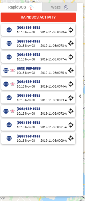
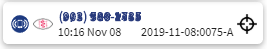
The Integrations tab is located on the middle-left of the Tracking screen. Hover over or click on the Integrations tab to open the Integrations panel. The RapidSOS tab within the Integrations panel shows any activity reported by RapidSOS related to active incidents. These activities are ordered by date/time (shown bottom-left), then by incident Id (shown bottom-right).
Integrations tab.
Most incidents include a caller's phone number. PULSE uses this phone number to check with RapidSOS for the presence of additional information. The RapidSOS Activity tab shows the following types of additional information provided by RapidSOS.
The ![]() target icon pans the map to a location related to the RapidSOS Activity.
target icon pans the map to a location related to the RapidSOS Activity.
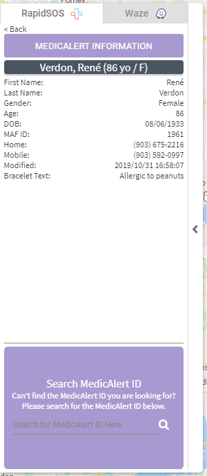
The MedicAlert Information panel shows MedicAlert information for the selected RapidSOS Activity. MedicAlert information is a profile related to a candidate.
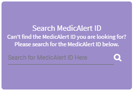
The MedicAlert ID Search allows you to search for a MedicAlert profile by MAF-ID (MedicAlert Foundation ID). To search:
Saved Views provides an efficient way of navigating to specific points on the map. A view is a named point that the map can be centered on.

Views tab will appear at the top of the map.
Views tab.

button will highlight green to indicate that the
name is valid.
button.
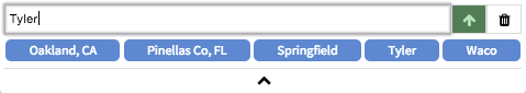
button will change to have an arrow pointing up.
button.
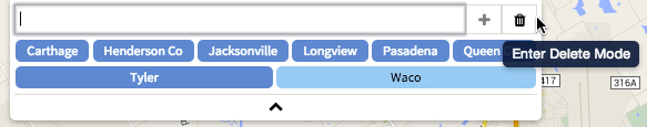
button.
button
will be highlighted with red as well to indicate that there are items
to delete.
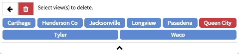
button will not
be highlighted.
button.
button
will no longer be highlighted.
button.
button is clicked.
The widget is designed to collapse when not in use so that it isn't in the way during normal use of the map.
Use the
button at the bottom of the widget to cause it to collapse.
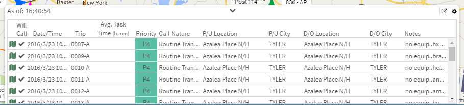
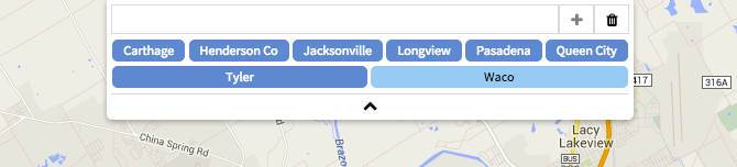
The Scheduled Calls in Queue widget can be enabled via the Widget Bar, and it will be displayed at the bottom of the Tracking screen.
This widget can be used to plan for scheduled calls throughout the current day and the next.
This widget is primarily passive in that it will primarily be for reference purposes, but there are 2 functions to be aware of.
By clicking the icon at the beginning of each row, a route will be displayed so that the distance can be taken into account when planning the call. How the route is displayed can be configured in the settings.
There must be a pickup and drop off location specified for the call for this feature to be available.
If planning for the next two days isn't enough the Scheduled Calls in Queue report can be access via the icon in the top right corner.
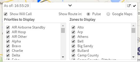
To enter the settings menu, click the icon in the top right corner.
The Integrations tab is located on the middle-left of the Tracking screen. Hovering over or clicking on the Integrations tab opens the Integrations panel. The Waze tab within the Integrations panel shows any traffic accidents reported by Waze. The items shown are only for a configured region that the dispatch center is interested in.
Integrations tab.
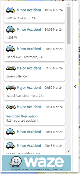
This widget is specifically for viewing Accidents reported by Waze, but there are other events that will be shown on the map. See all events reported by Waze.
Weather provides information according to user preferences.
There are nine sections -- Radar & Satellite, Forecasts, Observations, Outlooks, Roads, Severe, Storm Cells, Tropical Cyclones, and Tropical Invests.
To use this feature, go to the Layer Bar and click on “weather”.
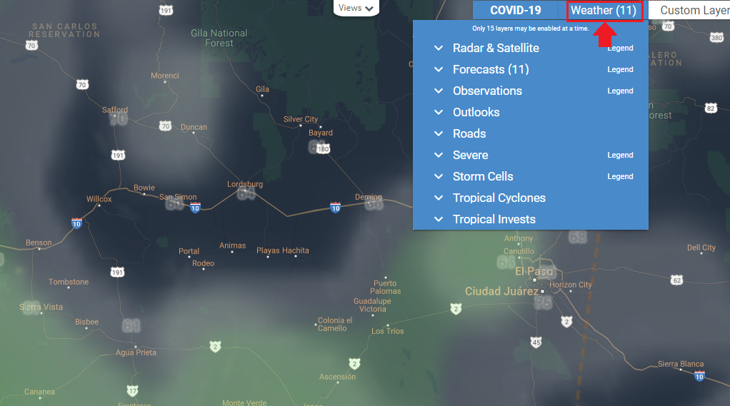
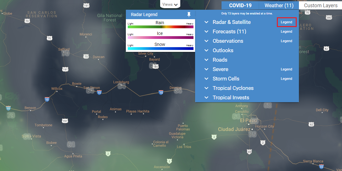
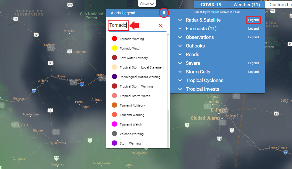
Some sections have a legend to give the user the definition of the colors used for each option in a layer. The list of legends can be displayed if you click on Legend. You can search for a specific legend entry by typing in the Alerts search box.
Each option under a layer has an opacity control. Opacity values range from 0 to 100, where 0 is completely transparent and 100 is opaque. Each layer will have a default opacity of 50.
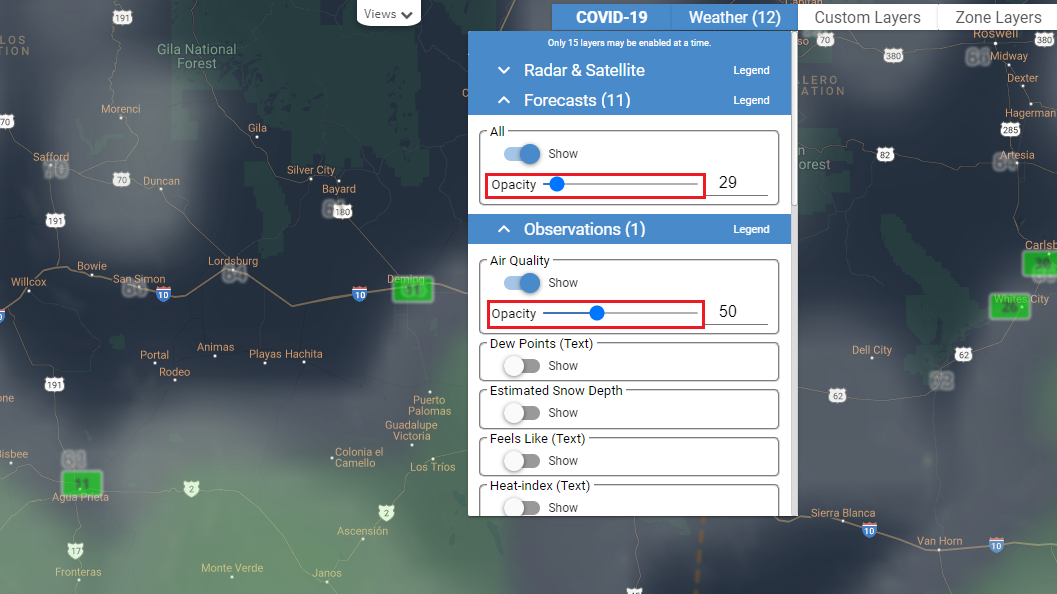
Up to fifteen layers can be enabled at a time. You can see the number of layers enabled next to the Weather widget label.
Radar -- Displays current weather conditions for the US and other regions around the world.
Forecast Radar -- Displays future weather conditions around the world.
Radar (Global) (Derived) -- Displays global radar derived from Radar. Covers the entire world.
Satellite (Geocolor) -- Displays the map in a color interpreted view of the globe which covers the entire world.
Satellite (Infrared) (Color) -- Displays the map in satellite view of the globe utilizing infrared which covers the entire world.
Forecast Satellite -- Displays the map with a global forecast satellite view.
Forecast High Temps (Text) -- Displays forecast high temperatures in text around the world.
Forecast Low Temps (Text) -- Displays forecast low temperatures in text around the world.
Forecast Precip Accum -- Displays forecast accumulated precipitation around the world.
Forecast Precip (1 Hour Intervals) -- Displays forecast accumulated precipitation in 1-hour intervals around the world.
Forecast Snow (1 Hour Intervals) -- Displays forecast snow in 1-hour intervals around the world.
Forecast Snow Accum -- Displays forecast accumulated snow in 1-hour intervals around the world.
Forecast Snow Depth -- Displays forecast accumulated snow depth in 1-hour intervals around the world.
Forecast Ice Accum -- Displays forecast accumulated ice in 1-hour intervals within the United States.
Forecast Surface Analysis -- Displays surface analysis(Lows, Highs, Fronts) within North America.
Forecast Surface Pressure (Text) -- Displays surface pressure text and amounts within North America.
Forecast Visibility -- Displays forecast visibility within the CONUS region (the U.S. excluding Alaska and Hawaii).
Air Quality -- Displays the air quality index which provides pollutant data around the world.
Dew Points (Text) -- Displays dew points in text around the world.
Estimated Snow Depth -- Displays estimated snow depth around the world.
Feels Like (Text) -- Displays what temperature it feels like within the CONUS region (the U.S. excluding Alaska and Hawaii).
Heat-index (Text) -- Displays the heat index in text around the world.
Humidity (Text) -- Displays the humidity in text around the world.
Precipitation -- Displays the precipitation within the United States.
River Gauge Observations -- Displays Enhanced data from rivers and lake gauges. Data includes recent crests, historical crests, and flood impacts within the United States.
Sea Surface Temperatures -- Displays the sea surface temperatures around the world.
Surface Analysis -- Displays the surface analysis within North America.
Surface Pressure (Text) -- Displays the surface pressure in text around the world.
Temperatures -- Displays the current temperatures around the world.
Temperatures (Text) -- Displays the current temperatures in numbers around the world.
Visibility -- Displays the visibility within the CONUS region (the U.S. excluding Alaska and Hawaii).
Wave Heights -- Displays the wave heights around the world.
Wind Chill (Text) -- Displays the wind chill in numbers around the world.
Wind Direction -- Displays the wind direction with arrows around the world.
Wind Gusts (Text) -- Displays the amount of wind gusts around the world.
Wind Speeds (Text) -- Displays the wind speed in numbers around the world.
Convective Outlook -- Displays SPC’s outlook for convective activity within the CONUS region (the U.S. excluding Alaska and Hawaii).
Fires Outlook -- Displays SPC’s outlook for weather conditions that will promote the spread of fires within the CONUS region (the U.S. excluding Alaska and Hawaii).
Fires Outlook (Dry Lightning) -- Displays SPC’s outlook for weather conditions that will promote the spread of fires by dry lightning within the CONUS region (the U.S. excluding Alaska and Hawaii).
Drought Monitor -- Displays official drought areas per the National Drought Mitigation Center within the United States.
6-10d Temp Outlook -- Displays a 6 to 10 day outlook of temperatures in the United States.
6-10d Precip Outlook -- Displays a 6 to 10 day outlook of precipitation in the United States.
Road Conditions -- Displays current road conditions in the United States.
Future Road Conditions -- Displays future road conditions within the United States, Southern Canada, and Northern Mexico.
Road Conditions Index -- Displays current road conditions indexes within the United States, Southern Canada, and Northern Mexico.
Future Road Conditions Index -- Displays future road conditions indexes within the United States, Southern Canada, and Northern Mexico.
Default -- Displays mild to severe weather events issued from the Canadian and US government within the United States, Canada, and Europe.
Severe -- Displays severe weather events issued from the Canadian and US government within the United States, Canada, and Europe.
Fire -- Displays Fire-related alerts only within the United States, Canada, and Europe.
Flood -- Displays Flood-related alerts only within the United States, Canada, and Europe.
Frost-Freeze -- Displays frost and freeze-related alerts only within the United States, Canada, and Europe.
Heat -- Displays heat-related alerts only within the United States, Canada, and Europe.
Wind -- Displays wind-related alerts only within the United States, Canada, and Europe.
Winter -- Displays winter-related alerts only within the United States, Canada, and Europe.
Lightning Strikes (Icons 15m) -- Displays cloud-to-ground lightning strikes as icons in the last 15 minutes around the world.
Lightning Strike Density -- Displays cloud-to-ground lightning strikes around the world.
Fires (Icons) -- Displays wildfires within the CONUS region (the U.S. excluding Alaska and Hawaii).
Default -- Displays observed storm cells and their forecast tracks per the NEXRAD radar
system in the United States.
General -- Displays storms cells that reflect general storms in the United States.
Hail -- Displays storms cells that reflect hail storms in the United States.
Major -- Displays storms cells that reflect major storms in the United States.
Rotating -- Displays storms cells that reflect rotating storms in the United States.
Tornado -- Displays storms cells that reflect tornado activity in the United States.
Default -- Displays information on active tropical cyclones around the world.
Names -- Displays the names of active tropical cyclones around the world.
Positions -- Displays the positions of active tropical cyclones around the world.
Position Icons -- Displays the positions as icons of active tropical cyclones around the world.
Track Lines -- Displays the track path of active tropical cyclones around the world.
Track Icons -- Displays the track path as icons of active tropical cyclones around the world.
Forecast Error Cones -- Displays the forecast error cones of active tropical cyclones around the world.
Forecast Lines -- Displays the forecast trail of active tropical cyclones around the world.
Forecast Icons -- Displays the forecast trail as icons of active tropical cyclones around the world.
Breakpoints -- Displays the breakpoints of active tropical cyclones around the East Pacific and Atlantic Oceans.
Default -- Displays the tropical invests around the world.
Names -- Displays the tropical invests by name around the world.
Icons -- Displays the tropical invests by icons around the world.
When selecting the weather layers, some of them come with other visual options
that can modify the view of the weather elements.
Dk -- Dark
Gfs -- Global Forecast System
Herr -- High-Resolution Rapid Refresh
Kuchera -- Kuchera SLR snow density
Lg -- Large
Nam -- North American Mesoscale Model
Ndfd -- National Digital Forecast Database
Rtma -- High-spatial and temporal resolution analysis for near-surface weather conditions
The PULSE Road Closures page allows you to view, create, and manage road closures entered via the Road Closures page.
To access the Road Closures page, your User must have the Road Closures [View] permission.
![]() Click here to watch a quick PULSE Road Closures video tutorial (no sound)
Click here to watch a quick PULSE Road Closures video tutorial (no sound)
To create a road closure, your User must have the Road Closures [Create] permission.
Road Closures page.
Add Closure button.
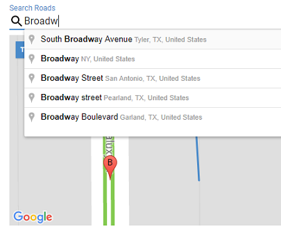
As you type in the Search Roads box, a list will provide suggestions. To search, select the best suggestion given.
 button on the map to Zoom in if needed.
Street Name is automatically selected based on the first road you click near.
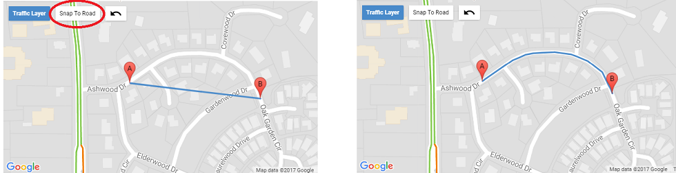
Click the Snap To Road button and Google Maps will map your road closure path to the contour of the road.
The road closure path cannot exceed 1200 meters (3937 feet).
Click the  icon to undo the last point of the road closure path. Undoing all points in the path will clear the Street Name selection.
End Date and End Time cannot be before the Begin Date and Begin Time.
End Date and End Time cannot be in the past.
Road closure must last at least five minutes.
Road closure duration cannot exceed 183 days.
All Lanes All Directions means traffic is completely blocked on this road.
All Lanes A-to-B means traffic is blocked on this road in the direction shown from A to B.
All Lanes B-to-A means traffic is blocked on this road in the direction shown from B to A.
From Intersection and To Intersection to provide additional information about what portion of the road is closed. If one field is filled out, then the other must also be.
Description to provide a brief description for the reason of the road closure.
Save button to create the road closure.
To edit a road closure, your User must have the Road Closures [Edit] permission.
Road Closure page.
Edit Closure button.
Update button.
A road closure moves through various states:
Road closures are created in the Pending state, and remain there until they are reviewed and approved by a user with the Road Closures [Approve] permission, or their end time is reached, whichever comes first.
Pending closures do not appear on the PULSE Tracking map.
When a user with the Road Closures [Approve] permission creates or edits a road closure, this road closure skips the Pending state and is considered Approved by the user.
When a user with the Road Closures [Approve] permission removes a pending road closure, this road closure moves to the Declined list.
When a road closure is approved by a user with the Road Closures [Approve] permission,
it enters the Approved state. Road closures remain in this state until their start time is reached.
When a user with the Road Closures [Approve] permission removes an approved road closure, this road closure moves to the Declined list.
When the start time of a road closure is reached, the closure becomes Active. Active road closures are included in the outgoing Waze feed. Once received by Waze and reported to PULSE, active road closures are visible on the PULSE Tracking map.
When a user with the Road Closures [Approve] permission removes an active road closure, this road closure's End Date and Time are set to the current date and time and this closure moves to the Inactive list.
When the end time of a road closure is reached, the road closure becomes Inactive. Declined road closures remain in the Declined state even after their end time is reached.
When a User with the Road Closures [Approve] permission declines a road closure the road closure becomes Declined. Declined closures do not appear on the PULSE Tracking map.
All of the resources that appear under the Resource Configuration menu provide configuration options for the Tracking page.
The following resources will be discussed:
- Assets - configure IMW assets
- Asset Types - configure types for IMW assets
- Custom Layers - upload or create points of interest
- Facilities - configure facilities loaded from CAD
- Layer Types - define types that can be assigned to Zone Layers
- Map Pages - upload geometries for Map Pages
- Posts - configure geofencing for posts
- Units - configure units for display
- Unit Statuses - configure display settings
- Vehicle Types - define types that can be assigned to vehicles
- Vehicles - set vehicle specific options
- Zone Layers - upload response zones
The Assets management page provides a listing of all assets that exist within the connected asset sources. See Assets for an overview of asset sources.
The asset list shows each asset by name, display name and/or alias as available.
To search for a particular asset in the asset list, enter text into the Search box above the asset list. The list is filtered to show only assets in the list that contain the search text.
To clear the search and show all assets, click the red X in the search box.
Clicking on an individual asset in the left pane will display details in the right pane.
* - For assets received via Motorola Solutions® Intelligent Middleware (IMW), the Display Name is populated by the Presence Notifier. If the Presence Notifier is not a part of your IMW solution, this value is not delivered to PULSE.
The Asset Types page provides a listing of all asset types that can be configured.
The asset type list shows each asset type by name.
To search for a particular asset type in the list, enter text into the Search box above the list. The list is filtered to show only asset types in the list that contain the search text.
To clear the search and show all asset types, click the red X in the search box.
Clicking on the CREATE button in the left pane will display a page with default Asset Type values in the right pane. The CREATE button is shown only when the user has a permission to create new Asset Types.
Clicking on an individual asset in the left pane will display details for that particular type in the right pane. To be able to edit the Asset Type details, user needs to have an edit permission for Asset Types.
To create a new Asset Type or submit changes to the existing one, click the Save button in the upper right corner.
To delete an Asset Type, click the red X button next to the Asset Type name in the list. The button is shown only when the user has a permission to delete Asset Types.
The Facility management page provides a listing of all facilities that exist within the connected CAD system.
If PULSE receives a geocoded address from the CAD for a facility, the facility's coordinates will no longer be configurable via PULSE.
Any facility that has a geocoded address will have a label in the top right
of the screen that reads Data Synced from CAD
to indicate that the
data was not entered via PULSE.
Clicking on an individual facility in the left pane will display details in the right pane.
Any non-editable fields that do not contain data from the CAD will be hidden until data is received.
Create layer types to differentiate response zones, districts, beats, etc. Currently, PULSE only uses the Layer Types as a way of categorizing layers.
The Custom Layers management page allows new layers to be added in two ways: ESRI based map layers can be uploaded using shapefiles or the user can create custom layers via the editor.
To upload new ESRI layers perform the following steps:
Only shapefiles consisting of Points or MultiPoints can be uploaded as custom layers.
Click the Upload button
On the right side of the screen a form will appear. The form contains
a field named Display Field: and a button for selecting
the files to upload. The Display Field is for entering
the name of the column within the shapefile that should be used to
name the uploaded layers. If no value is entered a default set of
names will be generated.
Enter a name in the Display Field text box.
Click the Select Files... button.
Select the required files (i.e., .shp, .dbf, .shx)
Click the Upload Files button.
Click the + button.
Click the hand button at the top of the map to position the map
Click the shape button at the top of the map to begin drawing.
Click anywhere on the map to place the first point.
Double Click or click the starting point to complete the shape.
Enter a name in the Layer Name field.
Click the Save button to submit the shape.
Click on a layer in the list to begin editing it.
A form will appear on the right side of the screen.
Make changes as necessary via the form on the right.
The name, stroke color, stroke weight, and fill color can be managed via this form.
Click the Save button to submit the changes.
Click on a layer in the list to select it.
Click the - button to delete it.
Custom layers cannot be deleted when they are in use by a Partnership or when used in View Filtering on a Role.
If enabled, a delay is automatically taken into account in Unit Recommendations if a unit is inside the defined area. To create a delay for the current custom layer:
Set the start time and the end time of the delay.
Set delay in minutes and seconds.
Delay can be set in the range of 1 to 120 minutes.
Choose the unit status(es) you want included or Select All
Click the ![]() button to add delay.
button to add delay.
You cannot define a delay that overlaps another one in the same custom layer.
Timeslices can be copied from one layer to another by using copy/paste buttons.
Mousing-over a delay clock in Active Responses and Unit Recommendations will show a tooltip of the response delay.
To upload new layers perform the following steps:
Verify the following are true about the shapefile being uploaded:
Code that contains the Response Zone Id for each layer in the file.
Enter a name in the Display Field text box.
This field is for entering the name of the column within the shapefile that should be used to name the uploaded layers. If no value is entered a default set of names will be generated.
Click the Select Files... button.
Select the required files (i.e., .shp, .dbf, .shx)
Click the Upload Files button.
Click on a layer in the list to begin editing it.
A form will appear on the right side of the screen.
Make changes as necessary via the form on the right.
The name, stroke color, stroke weight, and fill color can be managed via this form.
Click the Save button to submit the changes.
Click on a layer in the list to select it.
Click the - button to delete it.
A Map Page's polygon will be displayed on the Tracking and Replay pages for any incidents whose location is not geocoded with a latitude/longitude but have a map page code assigned. If a Code Pattern is specified, all Map Pages whose Code matches an incident's Map Page Code according to this pattern will be shown for that incident.
To upload new map pages perform the following steps:
Enter the Code Field.
This is a required field. This is used to pull the appropriate metadata from the shapefiles so that the incidents have something to match against.
Enter a name in the Display Field if known.
This is an optional field. If entered, the name of the Map Pages will be based on the value from the shapefile metadata with the specified display property.
Enter a pattern in the Code Pattern field if desired.
Leaving this field blank will require incidents to exactly match the code. By entering a pattern, incidents will match the map page based on the pattern.
Select Files... button.
Select the required files (.i.e., .shp, .dbf, .shx)
Upload Files button.
Click on a map page in the list to begin editing it.
A form will appear on the right side of the screen.
Make changes as necessary via the form on the right.
The name can be modified or the default location can be updated.
Click the Save button to submit the changes.
Click on a map page in the list to select it.
Click the - button to delete it.
The Post management page provides a listing of all post locations as listed within the CAD system or uploaded via The Genesis Group.
Clicking on an individual post in the left pane, will display details in the right pane.
Click the Geofence button
A dialog window will open with a map centered on the post with a heat map overlay indicating where past units have been when assigned to this post.
Use the Meters field to specify the radius around
the post that is acceptable for units to sit.
Acceptable range is 1 - 1000 meters.
Click the OK button when the desired radius is set
Click the Save button to save the geofence.
A geofence can be removed by setting the radius to 0.
Follow the steps listed above in the
Adding and Editing a Geofence section making sure to set
the Meters field to 0.
The Unit management page lists all units that are active within the connected CAD system.
Clicking on a unit in the list will display the following data:
This is the name of the unit that was pulled from the connected CAD.
This is a read-only field.
Toggling this feature on will prevent the selected unit from displaying, even if active and tracking in the CAD.
Unit will not show in Tracking, Replay, or Live Dashboards.
By default, all active units are taken into account when processing units to display in the Unit Recommendations widget.
Enabling this option will exclude the selected unit from the Unit Recommendations widget.
A travel mode can be selected to determine the ETEs in Unit Recommendations and Healthcare Facility Dashboard.
By default, all units are set to Driving Mode.
The background color to use for the unit's label can be selected. A demo label is shown for easier configuration.
This does not apply to the information window.
The Unit Statuses management page lists all active unit statuses on the connected CAD system.
PULSE Live allows users to further configure unit statuses with the following data:
This is the name of the unit status that was pulled from the connected CAD.
This is a read-only field.
Vehicle Types are categories that can be created for vehicles. The Vehicle Types page provides the ability to manage these categories.
These categories can be practically anything that makes sense for the connected CAD data.
These types are used on the Vehicle management page and are currently simply classifications.
The Vehicle management page lists all vehicles that are active in the connected CAD system.
Read-only
This value is not used in Tracking or Replay
PULSE Replay allows for supervisors and administrators to evaluate calls — from single-unit to system-wide — to verify the closest, most appropriate unit was assigned or diverted to a response and the most expedient route was taken.
Replay can be accessed by logging into PULSE, and clicking on the
Replay menu item. This will open Replay in its own
browser tab.
There are two options for running a replay.
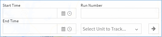
Time based Replay displays the map as it was during a given date range. Follow these steps to run a Time based Replay:
button
to initialize the Replay
A replay window of sixty (60) minutes is the maximum allowable duration.
Run based Replay uses a Run Number to find the appropriate date range for displaying data. Follow these steps to run a Run based Replay:
button
to initialize the Replay
The Time and Run based Replay are mutually exclusive; thus, when the Run Number is entered, if a date range was entered, the date range will be cleared and vice versa.
Replay has media controls that allow the data to be played, paused, sped up and slowed down. These controls are not visible until Replay has been initialized.
There are two views for the media controls.

The controls will collapse and move to the bottom of the screen after the replay is initialized.
This view provides a condensed control panel in order to maximize
the amount of space on the map. It can be expanded by clicking the
button.
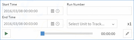
This view provides access to all controls including the date range and Run Number field.
This view can be used to reinitialize Replay with a different time
or run. It can be collapsed by clicking the
button.
The
(init) button
will not be visible until the date range or Run Number is changed.
Select a unit from the Select Unit to Track... field to have
the map center on the selected unit during the replay.
The Select Unit to Track... field has a list of all units that
are active units for the dispatch center. This means that units can be
selected that were not in use during the replay. If this occurs, the replay
will act like normal.
There are several widgets that are now available within Replay. Data will be displayed in these widgets as it was when it originally occurred with the notable exception of Optional Statuses as it is a simple utility widget.
The following widgets are available on Replay:
Note that there is an added control with the Waze widget that doesn't
appear on Tracking. Since Google Maps doesn't have historical traffic
data we instead use Waze to display traffic jams. Use the
Waze Traffic Layer button at the top of the map to enable
the traffic layer.
Replay can be initialized externally from various places within PULSE (e.g., Trip Details report). When initialized externally, the Run based Replay is used and the initialization controls are disabled; thus, externally initialized replays are specific to the run for which it was initialized.
If Replay has not finished buffering before moving the time slider ahead of the currently buffered section, play will begin/resume once buffering is complete.
There is a caveat for Stop Points to look out for when using Replay. Stop Points can only be set when a unit is in an 'At Scene' status as configured via the Unit Statuses configuration page. Be aware that if a unit status is currently configured to be an 'At Scene' status, but it was not during the interval for which Replay is running, stop points will not be available for units in the status in question and vice versa. Setting, moving, or deleting a stop point in Replay will only impact the Tracking map and any replay covering a period of time after the change was made.
The Contract management page allows new contracts to be entered into PULSE for tracking compliance.
The Details section of the contract identifies the contract, specifies the renewal and effective dates, the percentage of compliant responses to actually be compliant, and the length of time to which the percentage applies.
There is a Basis field that was originally used to
specify if the contract is Priority or Protocol based, but at the
moment PULSE does not support Protocol based contracts so the control
is disabled.
The layers tab allows response zones to be configured to determine what compliance standard should apply to a call.
Unit Types are used by Compliance Standards and can be used as a filter. The following options can be configured for each Unit Type:
The Call Types Tab provides a way to automatically apply a Unit Type filter to Unit Recommendations for Incidents with a specific Call Type. Using the Unit Recommendations Filter, users can override the Call Type automatic filter.
Compliance standards define response times for calls based on the Unit Type of an assigned unit and the Zone Layer in which the incident occurred.
The Standard Rules define the amount of time a unit has to respond to an assigned incident based on the incident's priority and whether or not the incident is considered an emergency. To check for violations the standard requires that a status be specified that starts the response clock and ends the response clock.
A dollar amount can be entered to record the fee incurred when a unit is late to an incident, but PULSE does not currently make use of this information.
Exemptions are reasons for which units may be excused for being late to an assigned call. These reasons can be added to a late call to indicate that it should be exempt from penalties via the Late Calls Workflow page.
Unit Types and any corresponding Layers must be configured prior to adding any new compliance standards.
+ button.
Details tab, enter a name for this contract.
Create button in the top right corner.
Layers tab.
Unit Types tab.
Compliance Standards
Add New Standard
Standard Rules (Standard Rules can only be added
after items 16 through 20 are completed)
Add Rule
22 - 29
Exemptions tab.
Create Exemption
32 - 35 for additional exemption reasons
At this point the contract is fully configured and PULSE will begin analyzing data against the contract for violations.
A contract can be modified by selecting it from the list on the left and following the same steps from above.
Deleting a contract is not as easy as creating and editing them. All
standards must be deleted, the layers must be removed, exemptions must
be deleted, and unit types must be deleted. At that point, the contract
can be fully deleted by selecting it from the list and clicking the
- button.
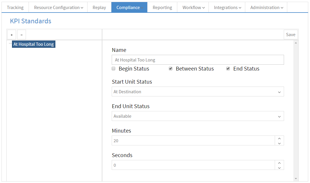
The KPI Standards page allows the creation of business KPIs that are based on the amount of time a unit spends in a configured set of statuses.
When a unit goes over the specified amount of time a KPI Violation occurs and the unit is flagged on the Tracking page.
Begin Status option onlyStart Unit StatusBetween Status option onlyStart Unit StatusEnd Unit StatusBegin Status optionBetween Status optionStart Unit StatusEnd Unit StatusBetween Status optionEnd Status optionStart Unit StatusEnd Unit StatusStart Status optionBetween Status optionEnd Status optionStart Unit StatusEnd Unit StatusThe Priority management page lists all priorities that have been received from the connected CAD.
Priorities in PULSE are used to color incidents and assigned units on the Tracking and Replay pages, and are used to configure contracts with standards that are used in determining compliance.
The name of the selected priority as it was received from the CAD.
Not Editable.
The type is used to categorize Priorities and acts as a filter. PULSE uses the type in the Scheduled Calls in Queue widget and report as well as in the Healthcare Facility Dashboard.
This option allows coloring the Unit Recommendations by Unit Priority Color or Label/Text Font Color.
PULSE Reporting provides Key Performance Indicators (KPI) and on-demand reports which deliver real-time feedback on the health of a system or individual contract areas. This allows for supervisors to make appropriate changes right away in service areas where compliance may be borderline.
The reports provided by Genesis are comprehensive. The PULSE user must choose the appropriate parameters for each report (if applicable) and once this is done, click Generate to view the report. Once the report is generated, it will display within the PULSE Reporting window.
Some reports require the user to page through them by using the left & right page progression tool at the top of the page. Reports can be printed or exported. Currently, reports can be exported into PDF or Excel for better viewing and/or data manipulation.
The report's information is restricted to units that the user's role has been configured to access. This filter is configured on the View Filtering section.
Access to reporting can be configured via the Roles page.
These reports use a reporting engine that allows parameters to be configured before running the report and will provides the ability to export or print the reports.
Static reports included in PULSE:
(*) The information of the reports marked with an asterisk (*) is restricted by the units that the role of the user is allowed to view. This filter is configured on the View Filtering section.
Interactive reports are either live reloading reports or provide additional functionality for the user.
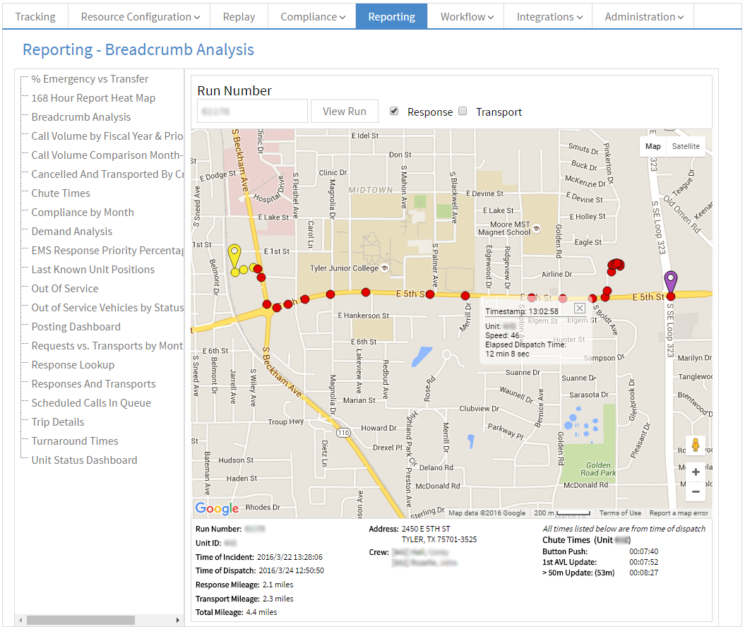
The Breadcrumb Analysis report allows a single trip to be analyzed on a
map via its AVL updates.
The report breaks the trip into the response and transport lengths and provides filters for both.
At the bottom of the report is a summary of the trip, and the map provides a view of all of the AVL updates received by PULSE.
The AVL updates appear as dots on the map and are colored based on how much time the assigned unit had been responding/transporting without reaching its destination. Currently, this is the same for all calls and is broken down as follows:
This report is accessible as long as the unit to be analyzed is enabled for the role of the user. This filter is configured on the View Filtering section.
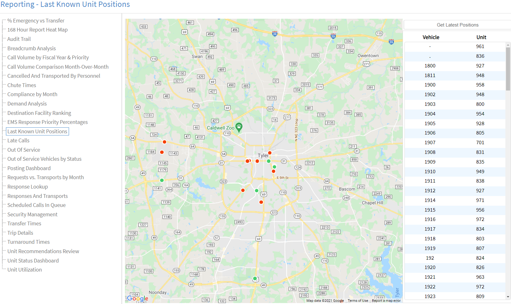
The Last Known Unit Positions report shows the last position tracked by PULSE for each unit/vehicle of the logged in user's dispatch center within the last 60 days.
Both active units, units that are currently being shown in Tracking, and inactive units will be displayed by this report. Active units are shown with green markers while inactive units are shown with red markers.
The report will run automatically when it is selected. Along the right side is a list of all the units that were returned and the Get Latest Positions button that allows the report to be refreshed.
To locate a unit on the map simply scroll to the unit in the list and click it. The map will automatically center on the selected unit, zoom in, and show the unit's details.
The unit's details can be closed by clicking on the close button in its top right corner. Any unit's details can be opened by clicking the unit in the list or by clicking on the map marker.
The unit's details includes the vehicle's name, the unit the vehicle is associated with, the latitude and longitude of the vehicle's last AVL update received by PULSE, and the time the last AVL update was recorded.
This report's information is restricted to units that the user's role has been configured to access. This filter is configured on the View Filtering section.

The Posting Dashboard is a live report that shows the current Posting Plan level for the various dispatch zones. This report acts as an aid for assigning units to posts.
Each column can be used to sort the report.
This report's information is restricted to units that the user's role has been configured to access. This filter is configured on the View Filtering section.
For calls that fail to meet the established standard(s) as set forth in Contracts, this report will provide a list of details related to the individual call(s). The ‘Run Number’ column is a hyperlink to the Breadcrumbs Report.
In the far right columns, if a late reason was selected from CAD (available with certain CAD systems), that reason is displayed here. Otherwise, a Late/Exempt reason can be selected. For more information on Exemptions, see the Contracts help section.
In the far right column of this report, a dispatcher or supervisor can set various options for the call.
These options include:
Not Late or Exempted.
A call cannot be considered Exempt without selecting a
reason from the drop-down list.
This report's information is restricted to units that the user's role has been configured to access. This filter is configured on the View Filtering section.
Integrations allow PULSE to add additional functionality that provides new benefits and information from trusted partners.
Waze is the world's largest community-based traffic and navigation app. Waze App user alerts, such as road closures and traffic accidents, will now be visible in PULSE Live, and CAD-generated data will be sent to Waze to be shown to their users.
PULSE Administrators can opt-out of sending their traffic incident information to Waze via the Configuration page. Once a site opts-out of sending traffic incident data to Waze, Waze data will no longer be available to the customer site.
These accidents are severe enough to cause prolonged delays or require rerouting of traffic.
These accidents may not cause prolonged delays or not require rerouting.
These events indicate that a road is closed and should be routed around.
Along with the icon PULSE will also use a red and white striping along the roads that are closed.
PULSE will show current traffic conditions reported by Waze using a severity scale to indicate the delay that should be expected on a given street.
AerisWeather is a powerful and flexible weather mapping platform giving you exactly the imagery and map overlay tiles you need. Provides information according to user preferences. There are three sections -- Radar, Alerts, and Storm Cells.
To enable this feature, go to the Weather Integration page and follow the instructions.
Shows areas of precipitation.
Displays the alerts on the map using a specific color for each alert.
Provides observed and forecast data of storm cell direction.
The Unit Tracker integration allows PULSE to receive unit positions directly from units instead of pulling them from the CAD. Units that are setup for this integration must have their vehicle mapped to the device that will be transmitting the positions. This mapping can be done via the Unit Tracking integration page.
This page will not be accessible if the integration has not been configured.
When the integration has been enabled the Unit Tracker page will appear
under the Integrations menu item.
The page provides the list of all vehicles, a list of all devices, and the configured mappings for the dispatch center.
To add a mapping simply select a vehicle, select a device, and click the
Add button.
A new mapping will appear in the list, and the Save button
will become enabled indicating that the mapping has not been saved yet.
Also, the vehicle and device will be removed from their respective lists
as all mappings are one-to-one.
Continue adding mappings as necessary, and when finished, click the
Save button to save all the configured mappings.
To remove a mapping, click on the desired mapping in the
Mappings list to select it, and then click the
Remove button to remove the mapping.
The device and vehicle that were part of the mapping will reappear in
their respective lists and the Save button will become
enabled indicating that the removal has not been saved.
Continue removing mappings as necessary, and when all modifications have
been made, click the Save button to save all changes.
At any time when changes have been made, the Cancel button
will be enabled. By clicking this button all modifications since the
last successful save will be cleared.
The Configuration page centralizes configuration options that are used throughout PULSE that are applied to all users from a dispatch center.
An SSP must be built into your CAD system or the plan provided to Genesis for upload into PULSE.
The data on this page is used throughout PULSE to reference your dispatch center.
Contact Genesis to establish a partnership with another PULSE customer. A signed written agreement between the two agencies must be provided to Genesis.
Partnerships allow the sharing of resources and data with other PULSE customers. You have full control over what is shared with each partner, and you can see what your partners are sharing with you.
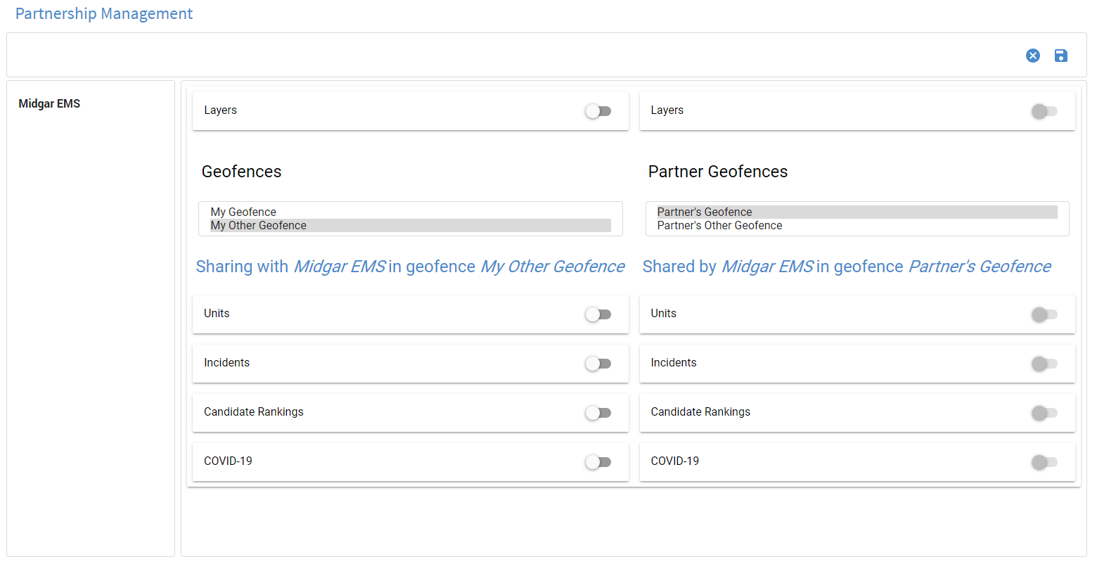

The toolbar provides 3 functions:
Notifications - any notifications about interactions performed by the user will be shown on this bar.
Cancel - the cancel button will clear all changes to all modified partners and will only be enabled when changes have been made.
Save - the save button will save all modifications made since the last save and will only be enabled when changes have been made.
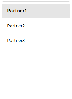
The Partner List provides access to all configured partners. Click on a partner in this list to view partner settings.
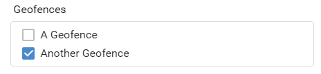
Select a geofence within which resources will be shared with the selected partner. Geofences may be created on the Custom Layers page.
Enabling Layers allows the selected partner to view your Custom and Zone Layers on their Tracking page.
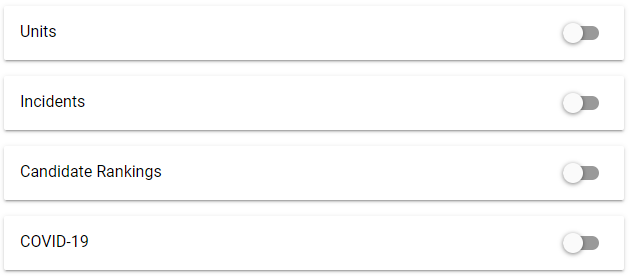
Enabling these options allows the selected partner to view various things within a geofence. By default all options are disabled. As each option is toggled on it will expand to display the additional options specific to the enabled resource. Continue reading below to see all available options.
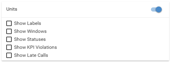
Once Units are enabled and the settings have been saved, all units configured to show on Tracking and within the selected geofence will begin showing for the selected Partner.
The options presented in the units section specify the way the units will appear on Tracking.
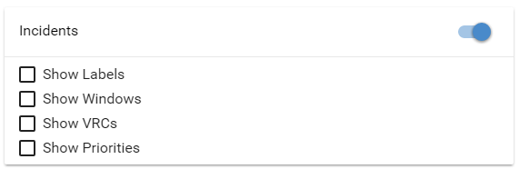
Once Incidents are enabled and the settings have been saved, all incidents that would show on your own Tracking page that are geocoded within the selected geofence will be visible on your partner's Tracking page. This section specifies how those incidents should be displayed for the selected partner.
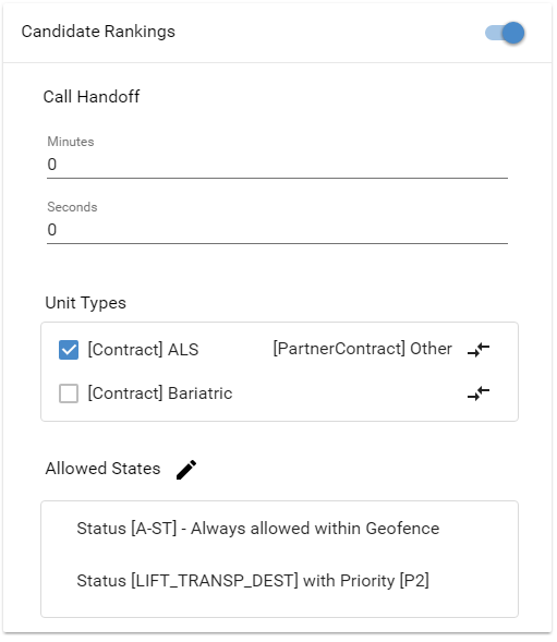
The Unit Recommendations section provides in-depth configuration options that will be applied to the Unit Recommendations widget.
The following options are available for configuring the Unit Recommendations widget:
To map a unit type, click on the icon at the end of the row and a window will be shown that allows the partner unit type to be selected. If there is already a mapped unit type there will also be an option to remove the mapping.
At least one Unit Type must be enabled. If no unit types are enabled your partner will not see any of your units in their recommendations.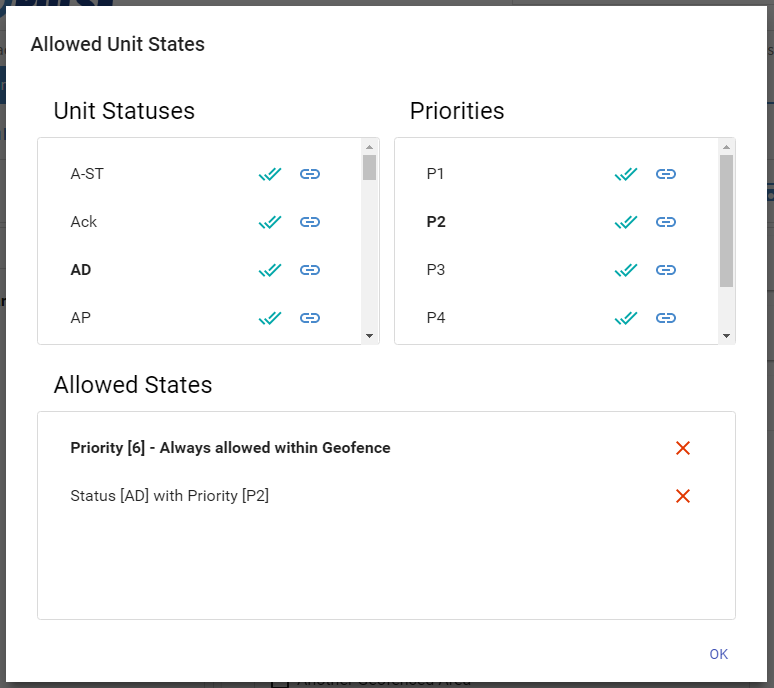
When the edit button is clicked the above dialog will be opened. This dialog allows unit statuses to be linked to priorities. There are a few different scenarios that can be configured via this window:
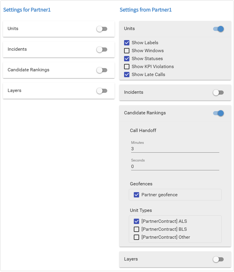
The partner panel is a view of the configuration that your partner has defined for you.
Personnel are aggregated from the customers CAD database and personnel listed here cannot be added or removed from PULSE.
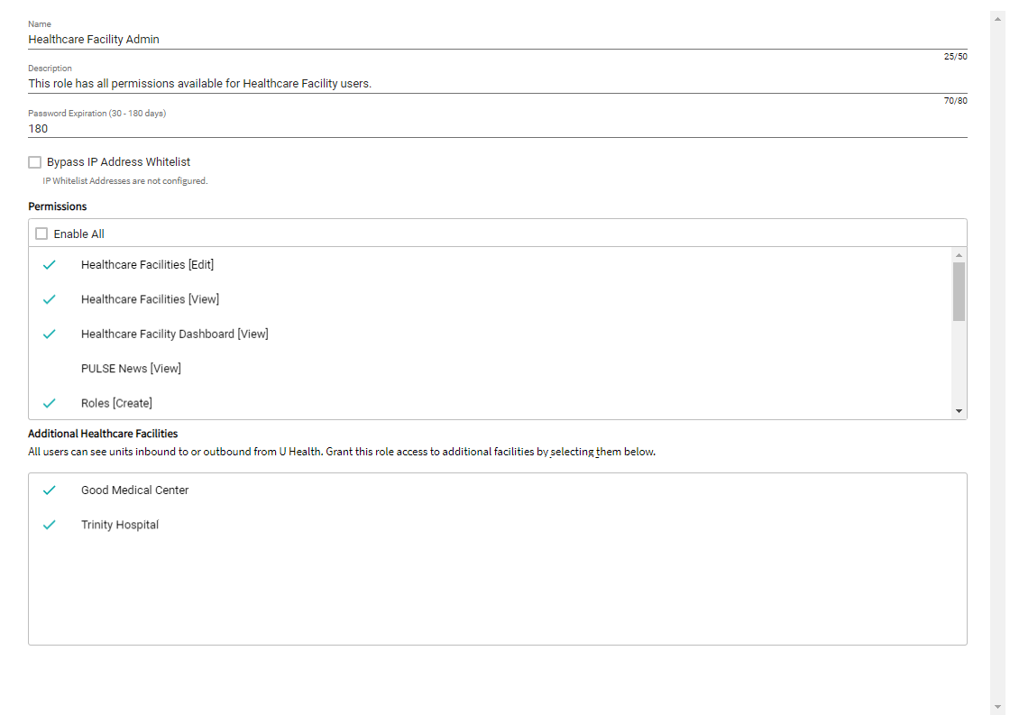
Security permissions within PULSE are established here.
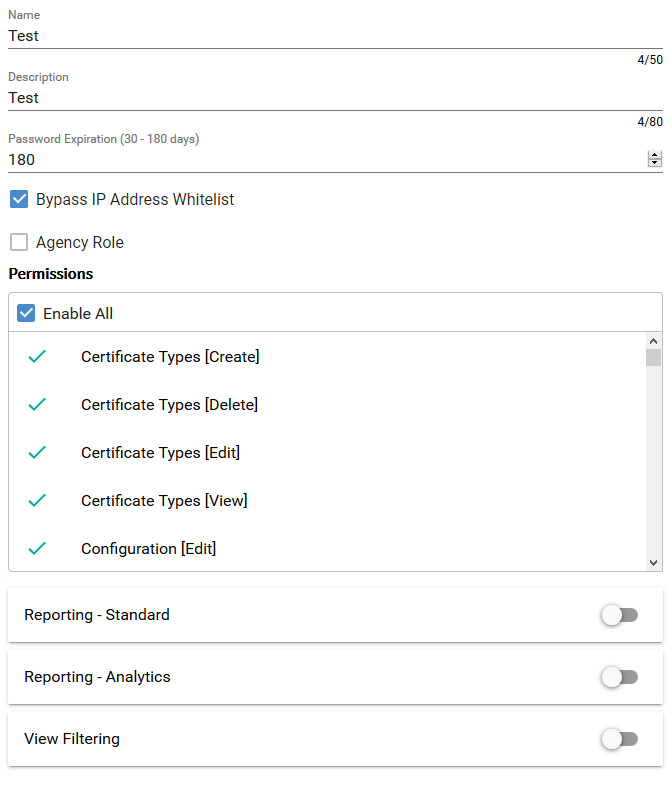
Name - Identifier for the Role. [Required, 50 character max]
Description - For clarifying the Role's purpose. [Optional, 80 character max]
Password Expiration Threshold - This specifies the number of days that a password will remain valid for users with this role. [Required, 30 minimum, 180 maximum, defaults to 180]
When the Password Expiration Threshold is restricted (i.e., number of days are reduced) it can cause the passwords of existing users to expire. When this happens a confirmation window will show the number of affected users. If the action confirmed then any users with expiring passwords will be logged out of PULSE and will have to reset their passwords before they will have access again.
Agency Role - Agency Roles are special roles that are used for limiting the available permissions.
Bypass IP Address Whitelist - Exempt specific roles from the IP Address Whitelist restriction to allow users with those roles to be logged in from anywhere. Configure the IP Address Whitelist on the Configuration page.
Permissions - This lists all available permissions that a user can be granted.
Reporting - Standard - This section allows reporting to be enabled for a user as well as the reports that the user will have access to.
View Filtering - View Filtering allows more granular configuration for what the user will see on Tracking and Replay.
Agency Roles restrict access to administration pages and reporting.
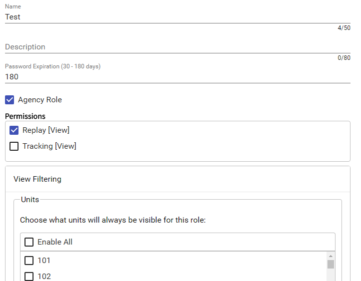
When this feature is enabled, any user with this role will only see units, incidents, VRCs, Map Pages, and Posts according to how the View Filter options are set. Most important to the view filter configuration is that including units from the Units list can significantly alter what data is displayed.
If any units are enabled in the Units list, only those units will be displayed regardless of their location, priority, or status. All other units will not be displayed, again regardless of their location, priority, or status. Any incidents assigned to the included units will also be displayed regardless of their location, priority, or status. Since In-Queue incidents are not associated with any unit, they and their VRCs and Map Pages along with any Posts will only be displayed if they satisfy the requirements defined by the Geofences, Priorities, and Unit Statuses as described below.
If no units are enabled in the Units list, then the only units displayed will be those operating within the selected geofences or those units outside the geofences but assigned to a call within the geofences.
Up to five (5) Custom Layers can be assigned to a single role. Any user-drawn (not uploaded) layers will be available as View Filter Geofences.
In addition to any geofence restrictions, units and incidents (along with their VRCs and Map Pages) will be displayed only if they meet the selected Priorities and Unit Status filter. If the AND option is selected, then a unit or incident must be at any one of the selected priorities AND at any one of the selected Unit Statuses. If the OR option is selected, then they only need be at either a selected priority OR a selected unit status.
The restrictions also apply to reports. Reports that include unit information only display information concerning the units that the role of the current user has access to.
The Security Management section allows an authorized user to generate a report showing all logins within a selected date range. Results can also be filtered using multiple parameters. An active session will highlight in green.
The Security Management page also allows authorized users to terminate an active session. This will cause all open instances of PULSE to logout for the selected user.
To terminate an active PULSE session, do the following:
Terminate Session link
All open sessions will receive a notification specifying that the session has been terminated and that the user will be logged out.
If the desired result is to terminate a user session and prevent the user from logging in with the selected user account, go to the User management page and reset the user's password.
PULSE users can be created, updated, and deleted via the Users page.
Any user assigned a Role with the
User [Edit] permission will be able to modify any existing
user account but their own.
User must have the User [Create] permission.
+ icon
The username must be a valid email address, and must be unique across PULSE.
Required for PULSE Mobile Access
Save button in the top right corner
This will create the new user and send an activation email to the email that was entered.
You'll notice that in the top right corner of the new user its
status can be seen. At this point the user is
Not Activated.
The following steps should be taken by each new user:
Activate button.
The account activation page will open in the user's default web browser.
Activate button
The account is now active and the user may log in.
When viewing this user in the Users page you will
now see Activated as its status.
When creating or changing a user's password, it must meet length, complexity, and reuse criteria.
(A - Z)
(0 - 9)
! @ # $ % & *
There are four ways that a user's passwords may be changed. The user can request a password change when they have forgotten it, change it via their account page when they are logged in, an administrator can change the password for them, or their password may be changed if they allow it to expire.
When the user submits their new password all of their active sessions will be terminated and they will have to log back in.
When the password is changed, all active sessions will be terminated and the user will have to log back in.
When the password is reset or the reset email is sent all of the user's current sessions will be terminated.
A user's password will expire after a configurable number of days as defined by their role. This interval is configured per role via the Roles page.
A user will receive four notification emails prior to their password expiring. These emails will be sent 14, 7, 3, and 1 day(s) before the expiration date.
Any time a user changes their password, their expiration date will reset. Should the user not change their password before it expires, the user's password will be reset and they will receive a password expiration email requiring them to change their password to continue using PULSE.
As is the case when the password is reset via other methods, when the user's password expires, all active sessions will be terminated and the user will have to reset their password via the password expiration email in order to log back in.
A user's account will be locked out after 5 failed attempts without a successful login.
After 3 consecutive failed attempts on the same browser and device, a user will see a message pointing them to the Forgot Password page. Once a user has 5 failed attempts (across all browsers/devices) without a successful login, their account will be locked. They will then receive an Account Locked email requiring them to contact their local PULSE administrator for the account to be unlocked. Once locked, the user will not be able to log in (even if they enter the correct password) until an Administrator unlocks the account.
To unlock the account, an Administrator will need to change or reset the user's password as described above in the Admin Password Management section.
The PULSE Healthcare Facility Dashboard page allows facilities in your coverage area to monitor inbound and outbound units. Each hospital in your coverage area can have its own dashboard. You can also view multiple facilities on the same dashboard.
If your facilities were manually imported by the PULSE team, and the facility you want is not listed, then send an updated list to PULSE Support.
Request Access button. PULSE will show the Request Healthcare Facility Access dialog.
This email address must not already be used in PULSE.
Request Access button. PULSE will send your request for access to PULSE support.
Upon approval, PULSE will sent a Pulse - Account Activation email to the email address that you provided.
If PULSE support does not have enough information on file to approve your request, PULSE support will contact you for more information.
Activate Your Healthcare Facility Dashboard Account button. PULSE will load the PULSE Account Activation view.
Please make sure to log out of any local PULSE sessions before clicking on the link in the email.
Activate button.
PULSE will log you in using your new PULSE Healthcare Facility Dashboard administrator account.
Dashboard menu item. PULSE will show the Dashboard view.
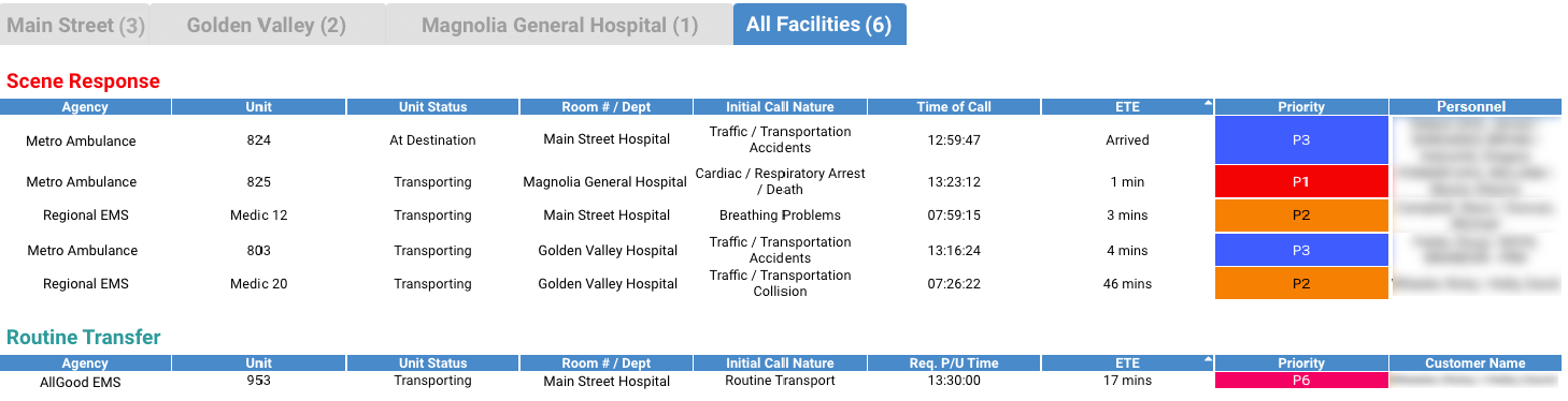
If your dashboard is linked to one or more additional facilities, the dashboard will show a tab for each facility and an All Facilities tab. Each facility tab shows dashboard information for the facility, grouped by priority type. You can configure priority types on the Priorities page in PULSE.
Click on the gear in the top-right corner of the dashboard to customize filter and column options.
The Dashboard view allows you to sort each column. Sorting applies to each priority type separately.
By linking facilities, you can view multiple facilities in a single dashboard. Only facilities that have an associated dashboard can be linked. To link facilities, follow the steps below:
The Healthcare Facility Dashboard section includes each facility for which you have create a healthcare facility dashboard.
Save button.
Dashboard menu item. PULSE will open the dashboard view, showing your healthcare facility and its linked healthcare facilities.
Role management for healthcare facility dashboards is similar to role management in the Role page in PULSE. If the PULSE admin has linked facilities to your dashboard, you can also control which roles are allowed to view the linked facilities by following the steps below:
Save button.